


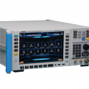

Ceyear1465A/B/C/D/F/H/L-V Vector Signal Generator
1465-V series signal generators has excellent vector modulation performance within the frequency range of 100kHz-67GHz. It has 200MHz internal modulation bandwidth and 2GHz external modulation real-time bandwidth, which can meet various modulation needs of wideband signals. The generator has excellent spectrum purity and output power specifications. The phase noise of 10GHz carrier @10kHz frequency offset can be reached to -126dBc/Hz, to meet high-level test needs which have strict requirements of testing signals. The generator also has excellent vector modulation accuracy and at the full frequency range the EVM is less than 1.4%(4Msps), which makes the generator be used in metrology purpose. The baseband signal generator can be set easily with flexible performance and many modulation formats. More than 20 kinds of common modulation formats are supported, such as PSK, QAM, FSK, ASK and so on.
FUNCTIONS & FEATURES
Main Characteristics
Broadband vector signal generatiLarge vector modulation bandwidth
High purity spectrum
Broadband and high-power output
Metrology grade vector modulation accuracy
Complete universal digital modulation format
Convenient touch screen control
Multiple control and function extension interfaces
Broadband vector signal generation
1465-V series signal generators can provide various signal testing solutions covering 3GHz/6GHz/10GHz/20GHz/40GHz/50GHz/67GHz to meet user’s specific needs in different fields. Especially, 1465L-V signal generator with 100kHz~67GHz frequency range can meet test needs of most users.
.jpg)
Vector Modulation Bandwidth
1465-V series signal generators can provide 200MHz internal modulation bandwidth and 2GHz external modulation bandwidth(above 3.2GHz carrier)vector signal generation function.
Arbitrary Wave Data Format Download
1465-V series signal generators support direct download and display of arbitrary waveforms. The file formats include Mat-File 5, ASCII, Binary, cap and csv. The generator has a 2GSa storage depth.
High Purity Spectrum
1465-V series signal generators are able to output extremely pure signal spectrum. The single side band phase noise of 10GHz carrier and 10kHz frequency offset has a typical value of -126dBc/Hz and 1GHz carrier and 10kHz frequency offset typically reaches -142dBc/Hz. It can be used for Doppler radar as well as high-performance receiver block and adjacent channel selectivity test. It also can be an ideal alternative device for local oscillator and low jitter timer.

Broadband and High-power Output
For high-power option H05, typical values for the maximum output power are +22dBm at 20GHz and +16dBm at 40GHz.There’s no need for an external amplifier when you need high power stimulus signal during test. And what’s more, the power accuracy and stability are better.
Metrology Grade Vector Modulation Accuracy
1465-V series signal generators has excellent vector modulation accuracy. The EVM is less than 1.4% (typical value<1.0%) at the frequency range 100kHz-40GHz, and EVM<2.5% (typical value<1.5%) at the frequency range 40GHz-67GHz.
Complete Universal Digital Modulation Format
1465-V series signal generators can provide real-time generation of universal digital modulation signals, including more than 20 kinds of modulations, such as PSK、QAM、FSK、MSK etc.
Convenient Touch Screen Control
A 10.1-inch LED display screen of 1280×800 resolution shows the instrument states information clearly. Conspicuous color matching, proper function division and various function panel buttons provide a fresh sight of vision, easy operation and higher test efficiency for you. Besides with the panel buttons, the instrument can be controlled independently by operating with enter knob, sliding or clicking on the touch screen, and using external keyboard or mouse.
Multiple Control and Function Extension Interfaces
Support various auxiliary interfaces such as USB, LAN, GPIB, Monitor. The USB interface can be used for data transmission and external keyboard/mouse. LAN and GPIB can be used for programmable control. The monitor connector can be used for external display when using a CRT or LCD.
TYPICAL APPLICATIONS
Communication system Test
1465-V series signal generator can generate high-performance user-defined modulation and basic digital modulation signal within frequency range of 100kHz~67GHz. The instrument can provide repeatable and reliable test signals for satellite communication. Its external wide bandwidth vector modulation and user-defined data features as well as additive noise function can create a real-world signal and help users to make product performance confirmation.
To Simulate Various Application Scenes for Radar and EM Environment
1465-V series signal generator has wide frequency range and high resolution(16bit)as well as powerful signal simulation function. It can generate complex sequences of various modulation formats by editing waveform segment under different scenes. Together with abundant functional synchronous trigger interface, it can simulate complex interference signal under actual environment and accomplish anti-interference test of radar equipment.
Provide Arbitrary Wave Modulation Signal
1465-V series signal generator has 2G sampling point waveform storage capacity. This feature can allow designer to generate a long-time test data, which may be more close to the reality. User can create one of the kinds of arbitrary wave data using the third party tools or software.
Receiver Test
1465-V series signal generator has a 140dB output dynamic range and extremely high frequency stability as well as 0.001Hz frequency resolution. It can output high-accuracy standard test signal which can solve parameter test problem such as sensitivity, dynamic range and channel selectivity to accomplish test of high-performance receiver used in radar, electronic warfare and communication equipment.
Local Oscillator Substitution
1465-V series signal generator has extremely high signal quality, thus can be used as an ideal device to substitute LO when testing transmitter and receiver and other systems. It will guarantee your test accuracy and creditability by avoiding negative influences that low-quality LO brings in.
Technical Specifications
| Frequency properties | |||||||||||||||||||||||||
| Frequency range | 1465A-V:100kHz~3GHz
(Min. frequency of 9kHz) 1465B-V:100kHz~6GHz (Min. frequency of 9kHz) 1465C-V:100kHz~10GHz 1465D-V:100kHz~20GHz 1465F-V:100kHz~40GHz (Max. frequency of 44GHz) 1465H-V:100kHz~50GHz 1465L-V:100kHz~67GHz |
Frequency | N(Internal YO harmonic order) | ||||||||||||||||||||||
| 100kHz≤f≤250MHz | 1/8 | ||||||||||||||||||||||||
| 250MHz<f≤500MHz | 1/16 | ||||||||||||||||||||||||
| 500MHz<f≤1GHz | 1/8 | ||||||||||||||||||||||||
| 1GHz<f≤2GHz | 1/4 | ||||||||||||||||||||||||
| 2GHz<f≤3.2GHz | 1/2 | ||||||||||||||||||||||||
| 3.2GHz<f≤10GHz | 1 | ||||||||||||||||||||||||
| 10GHz<f≤20GHz | 2 | ||||||||||||||||||||||||
| 20GHz<f≤28.5GHz | 3 | ||||||||||||||||||||||||
| 28.5GHz<f≤50GHz | 5 | ||||||||||||||||||||||||
| 50GHz<f≤67GHz | 10 | ||||||||||||||||||||||||
| Frequency
resolution |
0.001Hz | ||||||||||||||||||||||||
| Frequency
switching time |
<20ms | ||||||||||||||||||||||||
| Time-base aging rate(Typical value2) | 5×10 -10 /day(after 30-day continuous power-on) | ||||||||||||||||||||||||
| Reference output | Frequency | 10MHz | |||||||||||||||||||||||
| Power | >+4dBm,to 50Ω | ||||||||||||||||||||||||
| Reference input | Frequency | 1-50MHz,1Hz step | |||||||||||||||||||||||
| Power | -5dBm-+10dBm,50Ω impedance | ||||||||||||||||||||||||
| Sweep properties | |||||||||||||||||||||||||
| Sweep mode | Step sweep, List sweep, Analog sweep, Power sweep | ||||||||||||||||||||||||
| Analog sweep
(option H03) |
Max. sweep speed | 100kHz≤f≤500MHz | 25MHz/ms | ||||||||||||||||||||||
| 500MHz<f≤1GHz | 50MHz/ms | ||||||||||||||||||||||||
| 1GHz<f≤2GHz | 100MHz/ms | ||||||||||||||||||||||||
| 2GHz<f≤3.2GHz | 200MHz/ms | ||||||||||||||||||||||||
| 3.2GHz<f | 400MHz/ms | ||||||||||||||||||||||||
| Sweep
accuracy |
0.05 % Sweep width(for 100m, within the maximum width of 100ms as specified) | ||||||||||||||||||||||||
| Power properties | |||||||||||||||||||||||||
| Min. power | Model | Standard
package |
Option H01A/B | ||||||||||||||||||||||
| 1465A/B/C/D/F-V | -20dBm | -110dBm(-135dBm configurable) | |||||||||||||||||||||||
| 1465H/L-V | -20dBm | -90dBm(-110dBm configurable) | |||||||||||||||||||||||
| Max. power
(25±10°C) |
Frequency range | Standard
package |
H01A/B
programmable step attenuator option |
H05
high power output option |
Options H01A/B+H05 | ||||||||||||||||||||
| 1465A/B/C/D-V | |||||||||||||||||||||||||
| 100kHz≤f≤20GHz | 15dBm | 15dBm | 203dBm | 203dBm | |||||||||||||||||||||
| 1465F-V | |||||||||||||||||||||||||
| 100kHz≤f≤9GHz | 10dBm | 10dBm | 18dBm | 18dBm | |||||||||||||||||||||
| 9GHz<f≤30GHz | 10dBm | 10dBm | 15dBm | 15dBm | |||||||||||||||||||||
| 30GHz<f≤40GHz | 10dBm | 10dBm | 12dBm | 12dBm | |||||||||||||||||||||
| 1465H/L-V | |||||||||||||||||||||||||
| 100kHz≤f≤15GHz | 5dBm | 5dBm | 15dBm | 15dBm | |||||||||||||||||||||
| 15GHz<f≤30GHz | 5dBm | 5dBm | 12dBm | 12dBm | |||||||||||||||||||||
| 30GHz<f≤60GHz | 5dBm | 4dBm | 8dBm | 6dBm | |||||||||||||||||||||
| 60GHz<f≤67GHz | 4dBm | 3dBm | 6dBm | 4dBm | |||||||||||||||||||||
| Power accuracy
(25±10°C) |
Standard | ||||||||||||||||||||||||
| Power Frequency
(dBm) |
>10~20 | >-10~10 | -20~-10 | ||||||||||||||||||||||
| 100kHz≤f≤2GHz | ±0.8dB | ±0.6dB | ±1.5dB | ||||||||||||||||||||||
| 2GHz<f≤20GHz | ±0.8dB | ±0.8dB | ±1.5dB | ||||||||||||||||||||||
| 20GHz<f≤40GHz | ±1.0dB | ±0.9dB | ±1.8dB | ||||||||||||||||||||||
| 40GHz<f≤50GHz | — | ±1.3dB | ±1.8dB | ||||||||||||||||||||||
| 50GHz<f≤67GHz | — | ±1.5dB | ±2.0dB | ||||||||||||||||||||||
| H01A/B programmable step attenuator option | |||||||||||||||||||||||||
| Power Frequency
(dBm) |
>10~20 | >-10~10 | >-70~-10 | -90~-70 | |||||||||||||||||||||
| 100kHz≤f≤2GHz | ±0.8dB | ±0.6dB | ±0.7dB | ±1.5dB | |||||||||||||||||||||
| 2GHz<f≤20GHz | ±0.8dB | ±0.8dB | ±0.9dB | ±1.8dB | |||||||||||||||||||||
| 20GHz<f≤40GHz | ±1.0dB | ±0.9dB | ±1.0dB | ±2.0dB | |||||||||||||||||||||
| 40GHz<f≤50GHz | — | ±1.3dB | ±1.5dB | ±2.5dB | |||||||||||||||||||||
| 50GHz<f≤67GHz | — | ±1.5dB | ±1.8dB | ±3.0dB | |||||||||||||||||||||
| Power resolution | 0.01dB | ||||||||||||||||||||||||
| Power
temperature Stability |
0.02dB/℃(typical value) | ||||||||||||||||||||||||
| Output Impedance | 50Ω(Rating4) | ||||||||||||||||||||||||
| VSWR
(Internal fixed amplitude) (typical Value) |
100kHz≤f≤20GHz | <1.6 | |||||||||||||||||||||||
| 20GHz<f≤40GHz | <1.8 | ||||||||||||||||||||||||
| 40GHz<f≤67GHz | <2.0 | ||||||||||||||||||||||||
| Max. reverse power | 0.5W(0V DC)(rating) | ||||||||||||||||||||||||
| Spectrum purity5 | |||||||||||||||||||||||||
| Harmonic
(at +10dBm or Max. specified output power, whichever is lower) |
Frequency | Standard package | |||||||||||||||||||||||
| 100kHz≤f≤10MHz | <-25dBc | ||||||||||||||||||||||||
| 10MHz<f≤2GHz | <-30dBc | ||||||||||||||||||||||||
| 2GHz<f≤6GHz
(1465B) |
<-30dBc | ||||||||||||||||||||||||
| 2GHz<f≤20GHz | <-55dBc | ||||||||||||||||||||||||
| 20GHz<f≤67GHz | <-45dBc(typical value) | ||||||||||||||||||||||||
| Sub-harmonic
(at +10dBm or Max. specified output power, whichever is lower) |
100kHz≤f≤10GHz | None | |||||||||||||||||||||||
| 10GHz<f≤20GHz | <-60dBc | ||||||||||||||||||||||||
| 20GHz<f≤67GHz | <-45dBc | ||||||||||||||||||||||||
| Non-harmonic
(at 0dBm, beyond 3kHz offset) |
Frequency | Standard package | Option H04 | ||||||||||||||||||||||
| 100kHz≤f≤250MHz | <-58dBc | <-58dBc | |||||||||||||||||||||||
| 250MHz<f≤3.2GHz | <-74dBc | <-80dBc | |||||||||||||||||||||||
| 3.2GHz<f≤10GHz | <-62dBc | <-70dBc | |||||||||||||||||||||||
| 10GHz<f≤20GHz | <-56dBc | <-64dBc | |||||||||||||||||||||||
| 20GHz<f≤28.5GHz | <-52dBc | <-52dBc | |||||||||||||||||||||||
| 28.5GHz<f≤40GHz | <-45dBc | <-45dBc | |||||||||||||||||||||||
| 40GHz<f≤60GHz | <-42dBc | <-42dBc | |||||||||||||||||||||||
| Single side band
phase noise (dBc/Hz, +10dBm or Max. output power, whichever is smaller) |
Frequency | 1Hz | 10Hz | 100Hz | 1kHz | 10kHz | 100kHz | ||||||||||||||||||
| 100kHz≤f≤250MHz | — | — | -104 | -121 | -128 | -130 | |||||||||||||||||||
| 250MHz<f≤500MHz | — | — | -108 | -126 | -132 | -136 | |||||||||||||||||||
| 0.5 GHz<f≤1GHz | — | — | -101 | -121 | -130 | -130 | |||||||||||||||||||
| 1GHz<f≤2GHz | — | — | -96 | -115 | -124 | -124 | |||||||||||||||||||
| 2GHz<f≤3.2GHz | — | — | -92 | -111 | -120 | -120 | |||||||||||||||||||
| 3.2GHz<f≤10GHz | — | — | -81 | -101 | -110 | -110 | |||||||||||||||||||
| 10GHz<f≤20GHz | — | — | -75 | -95 | -104 | -104 | |||||||||||||||||||
| 20GHz<f≤28.5GHz | — | — | -69 | -89 | -98 | -98 | |||||||||||||||||||
| 28.5GHz<f≤50GHz | — | — | -64 | -84 | -92 | -92 | |||||||||||||||||||
| 50GHz<f≤67GHz | — | — | -57 | -77 | -86 | -86 | |||||||||||||||||||
| H04 ultra low phase noise option | |||||||||||||||||||||||||
| 100kHz≤f≤250MHz6 | -64 | -92 | -105 | -123 | -138 | -141 | |||||||||||||||||||
| 250MHz<f≤500MHz | -67 | -93 | -111 | -126 | -138 | -142 | |||||||||||||||||||
| 0.5GHz<f≤1GHz | -62 | -91 | -105 | -123 | -138 | -138 | |||||||||||||||||||
| 1GHz<f≤2GHz | -57 | -86 | -100 | -117 | -133 | -133 | |||||||||||||||||||
| 2GHz<f≤3.2GHz | -52 | -81 | -96 | -113 | -128 | -128 | |||||||||||||||||||
| 3.2GHz<f≤10GHz | -43 | -72 | -85 | -105 | -120 | -120 | |||||||||||||||||||
| 10GHz<f≤20GHz | -37 | -66 | -79 | -98 | -114 | -114 | |||||||||||||||||||
| 20GHz<f≤28.5GHz | -31 | -60 | -73 | -91 | -108 | -108 | |||||||||||||||||||
| 28.5GHz<f≤50GHz | -26 | -54 | -68 | -85 | -102 | -102 | |||||||||||||||||||
| 50GHz<f≤67GHz | -20 | -48 | -62 | -79 | -96 | -96 | |||||||||||||||||||
| Modulation properties | |||||||||||||||||||||||||
| Frequency
Modulation (option H02A) |
Maximum deviation:N×16MHz (N: YO harmonic number)
Accuracy (at 1kHz, N×20kHz≤deviation<N×800kHz): < ± (3.5%×set frequency offset + 20Hz) Modulation rate(3dB bandwidth, N×500kHz frequency offset): DC-10MHz Distortion(at 1kHz, N×20kHz≤deviations<N×800kHz): <1% |
||||||||||||||||||||||||
| Phase
Modulation (option H02A) |
Maximum deviation:
Normal mode: N×16rad (N: YO harmonic number) Broadband mode: N×1.6rad (N is YO harmonic number) Accuracy(at 1kHz, N×0.2rad≤deviations<N×8rad, normal mode) <± (5% of deviation + 0.01 rad) Modulation rate (3dB bandwidth,Broadband mode): DC~10MHz (typical value) Distortion (at 1kHz, N×0.8rad≤deviations<N×8rad, THD): <1% |
||||||||||||||||||||||||
| Amplitude
modulation (option H02A) |
Max. depth:>90%
Modulation rate (3 dB bandwidth, 30% modulation depth): DC~100kHz Accuracy (1kHz modulation rate, 30% modulation depth): ±(6% of setting + 1%) Distortion (1kHz modulation rate, linear mode, THD, 30% modulation depth): <1.5% |
||||||||||||||||||||||||
| Pulse Modulation
(option H02B) |
500MHz-3.2GHz | >3.2GHz | |||||||||||||||||||||||
| Switch ratio | >80dB | >80dB | |||||||||||||||||||||||
| Rise and fall time | <20ns | <20ns | |||||||||||||||||||||||
| Min. pulse width with ALC on | 1μs | 1μs | |||||||||||||||||||||||
| Min. pulse width with ALC off | 0.1μs | 0.1μs | |||||||||||||||||||||||
| Narrow
pulse Modulation (option H02C) |
50MHz-3.2GHz | >3.2GHz | |||||||||||||||||||||||
| Switch ratio | >80dB | >80dB | |||||||||||||||||||||||
| Rise and fall time | <15ns | <10ns | |||||||||||||||||||||||
| Min. pulse width with ALC on | 1μs | 1μs | |||||||||||||||||||||||
| Min. pulse width with ALC off | 30ns | 20ns | |||||||||||||||||||||||
| Internal modulation signal generator
(option H02A/B/C) |
There are 3 independent signals respectively for frequency/phase modulation, amplitude modulation and low frequency output signals.
Waveform: sine, square, triangle, Sawtooth, noise, double sine, sweep sine. Frequency range: DC~10MHz for sine, double sine, sweep sine; 0.1Hz~100kHz for square, triangle, sawtooth. Frequency resolution: 0.1Hz Low frequency output: Amplitude: 0-5Vpeak(rating), to 50Ω load. Pulse modulation signal: pulse width: 20ns-(42s-10ns); pulse period: 100ns-42s; resolution: 10ns. |
||||||||||||||||||||||||
| Vector modulation accuracy(after calibration, 25℃±10℃)
(4Msps, root-Nyquist, α=0.3, QPSK, 0dBm) |
1465A/B/C/D/F-V | 50MHz-40GHz(or max. frequency) | EVM(RMS%)<1.4% | ||||||||||||||||||||||
| 1465H/L-V | 50MHz-40GHz | EVM(RMS%)<1.4% | |||||||||||||||||||||||
| 40GHz-67GHz(or max. frequency) | EVM(RMS%)<2.5% | ||||||||||||||||||||||||
| Internal modulation bandwidth | (Carrier 900MHz, 1.8GHz, 2.4GHz, 6GHz, 18GHz, 35GHz, 50GHz)
Standard package: 120MHz(Multi-tone, Tone quantity: 51, Frequency space: 2.4MHz,±3dB bandwidth); H3 large modulation bandwidth option: 200MHz(Multi-tone, Tone quantity: 51, Frequency space: 4MHz, ±3dB bandwidth). |
||||||||||||||||||||||||
| External modulation Bandwidth | (Carrier 900MHz、1.8GHz、2.4GHz、6GHz、18GHz、35GHz、50GHz)
200MHz(ALC OFF, input 100mVrms sine to channel I, ±4dB bandwidth) |
||||||||||||||||||||||||
| External wide modulation Bandwidth
(option H33) |
(6GHz、18GHz、35GHz、50GHz)
2GHz(ALC OFF, input 100mVrms sine to channel I, ±4dB bandwidth) |
||||||||||||||||||||||||
| Internal baseband signal generator | Channel quantities:2(I and Q)
Max. symbol rate: standard package: 60Msps(Max. 4bit/symbol) option H31: 125Msps(Max. 4bit/symbol) Baseband waveform internal memory: standard package: 1GSa option H32: 2GSa Modulation format: PSK: BPSK, QPSK, OQPSK, π/4 DQPSK, D8PSK, 16PSK; QAM: 4, 16, 32, 64, 128, 256, 512, 1024; FSK: 2, 4, 8, 16; ASK;MSK; Arbitrary wave modulation. Dual-tone mode max. frequency offset: 200MHz EVM: <1.0%(typical value)(RMS%, Symbol rate 4Msps, root-Nyquist, α=0.3, QPSK) |
||||||||||||||||||||||||
| General properties | |||||||||||||||||||||||||
| RF output port | 1465A/B/C-V: N(female), impedance 50Ω.
1465D-V: 3.5mm(male), N(female)(option H91), impedance 50Ω. 1465F-V: 2.4mm(male), impedance 50Ω. 1465H/L-V: 1.85mm(male), impedance 50Ω. |
||||||||||||||||||||||||
| Max. Physical Dimension | W×H×D: 517mm×192mm×550mm | ||||||||||||||||||||||||
| Weight | <28 kg(as per model and option configuration) | ||||||||||||||||||||||||
| Power Supply | 100-120VAC, 50-60Hz; or 200-240VAC, 50~60Hz(self-adaptive) | ||||||||||||||||||||||||
| Power Consumption | <400W | ||||||||||||||||||||||||
| Temperature Range | Working temperature:0℃~+50℃;Storage temperature:-40℃~+70℃ | ||||||||||||||||||||||||
Notes:
1. When 1465-V series signal generator is under environment temperature for 2 hours, attenuator is automatically coupling(or ALC power>-5dBm)after 30 minutes warm-up time. The generator meets every parameter performance within given working temperature.
2. Typical value is a supplementary characteristic just for user’s reference. These specifications are not guaranteed.
3. 1465B-V is +16dBm.
4. Rating value is an expected performance, or used to describe the product performance which is useful but not included in product performance warranty.
5. Spectral purity parameter is tested in a certain frequency without any modulation.
Bm. The working frequency range of option H06 is greater than 100MHz,so there’s no tested specification under 100MHz.
Related products


RF & Microwave
RF & Microwave


RF & Microwave


RF & Microwave


RF & Microwave

RF & Microwave
RF & Microwave