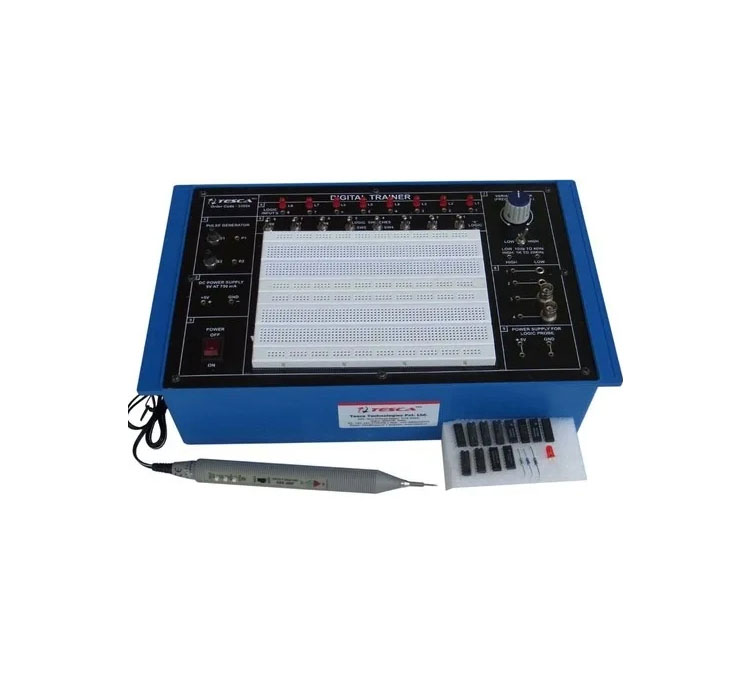


TESCA Digital – Analog Lab
The DIGITAL-ANALOG LAB is intended for elementary as well as advance training of Digital & Analog electronics. The trainer covers regular digital & analog circuits by solder-less interconnections on breadboard and as well as compatible with all optional modules, through use of 2mm brass terminals and patch cords. Various clock generators, logic level input/output indicators and DC regulated power supplies etc. are in-built. The unit housed in attractive enclosure is supplied with mains cord, patch cords, Instruction manual and Component Set.
- Bread Board : Unique solder-less large size, spring loaded breadboard consisting of two Terminal Strips with 1280 tie points and 4 Distribution Strip swith 100 tie points each, totaling to 1680 tie points. (Size:112mm x170mm)
- Regulated DC Power Supply : 5 V at 1 Amp, -5 V at 1Amp, 12 V/ 0 to 20V at 500mA, and -12 V/ 0 to -20 V at 500 mA
- AC Supply : 5-0-5V, 10-0-10V at 100mA. Can be used as 5V, 10V, 15V, 20V, and also as center tap
- Function Generator : Sine / Square / Traingular / Pulse waveform frequency 1 Hz to 110 Khz in 5 Steps. Variable in between steps. Sine / Square / Traingular waveform output 50mV ~ 10Vpp variable
- Clock Generators : 0.1Hz and 100 Hz, Independent fixed TTL 5V outputs
- Variable Clock Generators : low frequency variable clock 1 Hz to 10 Hz Fixed TTL 5V output
- Pulser Switch : 2 independent buffered bounce free manual pulser (useful for freezing the action of each stage of the counter after every clock pulse)
- Data Switch : 16 independent logic level inputs to select High / Low TTL levels, each with a LED to indicate high / low status and termination
- Logic Indicators : 16 independent buffered logic level indicators for High / Low status indication of digital outputs
- Speaker : 8 ohms miniature speaker with terminations
- Digital meter (3½Digit) : Dual range DC Voltmeter 0-20V / Ammeter 0-200mA
- Continuity Tester : For testing the continuity. Provided with Beeper Sound
- Potentiometers : 6 Potentiometers (1K, 22K, 47k, 100K, 100K and 1Meg) with terminals
- BNC to banana adapter : 2 Nos. BNC to 2 channel banana adapter
- Computer interface : Facilities connecting your trainer to either Rs232 communication port of PC ADAPTER using 25 pin (male) connector through 25 nos. of 2 mm banana sockets
- On Board Switches : 2 Switches singal pole double through
- Connecting terminals : 2 / 4 connecting terminals
- Seven segment LED Display : 2 Nos. BCD to Seven Segment Decoder/ Driver IC with terminals
- LED Bar Graph : With 10 LED Indicators and 20 termination
- Logic Probe : Logic level indicator for TTL/CMOS
- Power : 230 V ± 10%, 50 Hz
- Accessories : Mains cord, Operating and Experimental manual, Red & Black patch cords (2mm with Pin) 10 each, Red & Black patch cord (Pin to Pin) 10 each & Component Set
- Instruction manual : Strongly supported by detailed operating instructions
- Weight : 6 Kg. (Approx)
- Dimension : W 412 x H 150 x D 310
Experimental Coverage:
- Analog
- Study of Diodes in DC circuits
- Study of Light Emitting Diodes in DC Circuits
- Study of Half wave rectifier
- Study of Full wave rectifier
- Study of Zener Diode as a voltage regulator
- Study of transistor series voltage regulator
- Study of transistor shunt voltage regulator
- Study of Low pass filter
- Study of High pass filter
- Study of band pass filter
- Study of CE configuration of NPN transistor
- Study of CB configuration of NPN transistor
- Study of CE amplifier
- Study of Monostable multivibrator using transistor
- Study of Bistable multivibrator using transistor
- Study of Astable multivibrator using transistor
- Digital
- Logic gates operation
- To verify De-morgan’s theorem With boolean logic equations
- Binary to Gray code conversion
- Gray code to Binary conversion
- Binary to Excess-3 code conversion
- Binary Addition and Subtractor
- Binary Multiplier
- EX-OR gate implementation
- Application of EX-OR gate
- Johnson Counter
- To verify the dual nature of Logic Gates
- Study of Flip-Flops RS, JK, D&T
- Multiplexer and Demultiplexer
- 4 Bit Binary up and down counter
- Study of 8 to 3 Line Encoder
- Study of 3 to 8 Line Decoder
- Study of Shift Register (SIPO)
- CMOS-TTL Interfacing
- Study of Crystal oscillator
- Study of pulse stretcher circuit
Related products


Education Equipment


Education Equipment

Education Equipment

Education Equipment
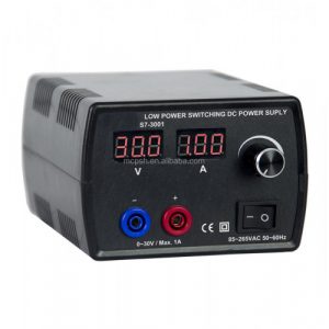
Citek S7-1201 | SWITCHING POWER SUPPLY 3V, 4.5V, 6V, 7.5V, 9V, 12V 1.5A


Education Equipment

